 |||
|||
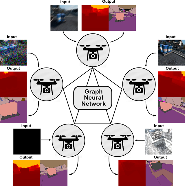
We use Deep Reinforcement Learning to train a policy network that outputs the next-view positions in order to obtain good inspection performances for Autonomous Drone Inspection application.
Drone Inspection has a wide range of industrial applications. In the industry, people use drones to inspect facilities where human operators may have difficulty and risk their lives to reach, especially for high infrastructures such as bridges, windmills, or nuclear power plants (see Fig. 1). With the help of the drones, the human operator can control the drone remotely and focus on the intelligent parts of the inspection work, which are:
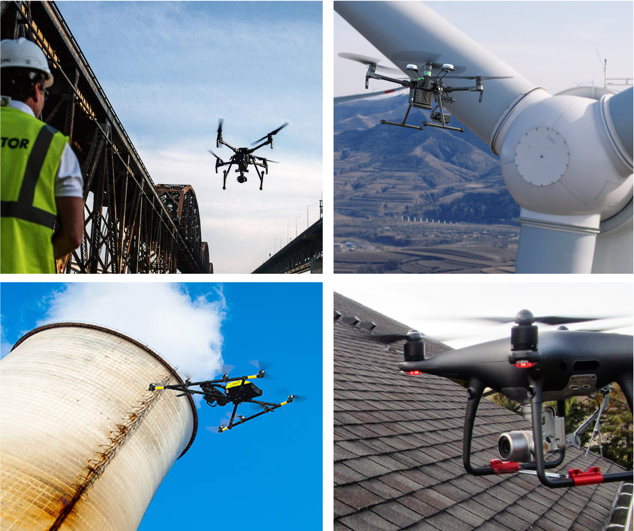 Fig. 1 Industrial applications of drone inspection including bridge inspection, windmill inspection, nuclear powerplant inspection and rooftop inspection.
With the recent development of robotics, we have obtained significant progress on various autonomous robots. Since the human pilots suffer so much and are prone to error with the drone inspection task, how about making it fully autonomous? Can we build a Autonomous Drone Inspection system which conducts:
Autonomous Inspection Evaluation: The system takes the sensor measurements and uses the inference algorithm (it could be learning-based or non-learning-based) to obtain the quality. The quality can be represented by a vector of values according to the evaluation metric or a dense map that reflects the location details of the result.
Autonomous Next-best-view Planning: The system plans the next viewing position and direction for better inspection performance according to the local information and global information. There are two ways to utilize global information or local information in practice. a) If the drone can have the global map (even a coarse map) of the environment that it will inspect, we can plan a global trajectory according to the 3D reconstruction of the environment. b) If the drone does not have the global map (which is more realistic for the first-time job), the drone will determine the next-best view according to the current sensor measurement and a limited local map.
Of course, we can also combine these two approaches. First, we can do a coarse scanning of the environment to obtain an initial trajectory. Second, we refine the trajectory while conducting the inspection according to the finer sensor measurements.
Autonomous Navigation: The system guides the drone from one 3D position to another 3D position with 4 Degrees-of-Freedoms (x, y, z, and yaw) with collision avoidance. In order to accomplish it, the system should have a self-localization, which can be accomplished by GPS or Visual-Inertial-Odometry (VIO) with an onboard camera and an Inertial Measurement Unit (IMU) in GNSS-denied scenarios. The system should control the drone to move by translation and yaw-axis rotation. The system should also learn to detect the distance to the obstacle and plan the trajectory to avoid it with the help of a stereo depth-sensing camera.
Since we are working with Size, Weight, and Power (SWaP) constrained aerial vehicles, there are many challenges in each system component.
For the Autonomous Inspection Evaluation, if we consider the camera as the primary sensor, traditional computer vision methods have difficulty being robust to different noises and a variety of environments. That is where deep learning-based methods stand out. In the last decade, Deep Neural Network (DNN)-driven methods have outperformed object detection, object pose estimation, and semantic segmentation. These visual tasks are the common tasks for drone inspection applications. What about integrating learning-based inspection evaluation method with an autonomous drone inspection pipeline?
For the Autonomous Next-best-view Planning, different works have been proposed in order to suit the purpose of different tasks. There are two kinds of next-best-view local planning. One is for exploration path planners. These works usually address the 2D next-best-view planning problem. Another kind of the next-best-view planning is for 3D reconstruction. Based on different environment representations (such as surfels or point clouds), they explore the frontier of the map to gain more knowledge of the unknown part. However, these methods are highly specialized for their task, and it is hard to generalize these works to other tasks or scenarios.
Deep Reinforcement Learning (DRL) teaches the agent how to act based on observation. If we model the autonomous drone inspection problem as a DRL problem, we can use this paradigm to apply it to different use cases. What about having a general next-best-view planning algorithm powered by deep reinforcement learning, which takes the sensor measurement and outputs the next position?
For the Autonomous Navigation, GPS-enabled navigation has been deployed in many robotics tasks. However, we want to argue that a GPSS-denied environment is quite common for autonomous drone inspection. First, most drone inspection demands the drone to be close to the target object, which raises a safety concern for GPS-enabled navigation due to the precision of the GPS localization. Second, inspecting these man-made objects requires the drone to fly under the object structure, blocking the GPS signal, such as the bottom of the bridge. Thus, we need a GNSS-denied navigation approach. How about using a VIO-based navigation to maintain precise localization and control of the aerial vehicle?
Therefore, we propose an Autonomous Drone Inspection framework with Deep Reinforcement Learning. This framework uses the image as the sensor measurement and produces the next-view position action according to the current sensor measurements. The action policy is trained with deep reinforcement learning by interacting with the real-world environment and designed reward which encourages safety movements and good inspection performance.
 Fig. 2 System architecture. Robots receive the RGB image from the environment as the observation and the reward according to the safety mechanism and the object detection performance. The robot acts by moving to the next position on the hemisphere around the target scene.
Our experiment uses object detection as the inspection task to demonstrate our proposed framework. We illustrate our system architecture in Fig. 2.
For the Autonomous Inspection Evaluation, we use a trained YOLOv3-based drone detector as the inference model. The object detector outputs bounding boxes with confidence scores and the object classes. We assume there is one target drone in the environment. We choose the drone bounding boxes with the highest score as the inspection target. To evaluate the result from the detector, we use a VICON motion capture system to obtain the detection ground truth.
For the Autonomous Next-best-view Planning, we model the problem in an RL manner.
Agent: a drone with onboard computation, optical flow camera, stereo gray-scale camera, high-resolution RGB camera and Inertial Measurement Unit (IMU).
Environment: a set of white blocks and a target drone. The white blocks block the drone from some viewing directions.
Observation: RGB camera obtained from the front high-resolution RGB camera.
Action: the relative position on the semi-sphere around the target environment. The action is a vector of two continuous values representing latitude and longitude. We use a CNN-MLP policy network to generate the action from the image sensor measurement in Fig. 3. In our experiment, we use (Soft-Actor-Critic) SAC as the off-policy deep reinforcement learning algorithm to train the policy network.
Reward: the reward combines safety score and detection performance. We show the specific reward design in Tab. 1. The ‘Safe Movement’ score penalizes dangerous action, which navigates the drone to collide on the obstacles. The ‘Detection Confidence’ and ‘Detection IOU’ encourage the robot to find a view with better detection results. The ‘Center Position Quality’ serves as a hint to help the drone centralize the target drone in the image, which imitates the visual servoing task to simplify the task.
For the Autonomous Navigation, the drone uses a downward optical flow camera and onboard IMU to measure Visual-Inertial-Odometry (VIO). The VIO runs at 30 Hz, and we further use an Unscented Kalman Filter (UKF) to filter the IMU measurement stream (500 Hz) with the output stream of VIO to obtain a 500 Hz pose estimation for high-speed control. We use the stereo camera to generate the depth map for obstacle avoidance. We use minimum snap trajectory generation to control the drone navigation between two spatial locations.
 Fig. 3 Policy Network architecture. SAC uses an Actor-Critic structure. The actor uses 3-layer CNN to extract the feature from the input image and FC layers to predict the distribution of optimal action, assuming it fits a multi-variable Gaussian distribution. It will output the predicted mean values and the log values of predicted standard deviations. During the training process, it will sample from this distribution to output an action vector. The critic uses the same structure for CNN and the first FC layer, while it attaches two critic networks (1-layer FC) after the feature extractor to output the rewards. The input of critic networks is the combination of action and feature. The double critic networks are to reduce overestimation.
 Tab. 1 Reward Design. The targets of the reward are 1) Have a good object detection performance. 2) Navigate the drone without bumping into the obstacle.
We implement our system as integration of ROS operating system and OpenAI Gym, the policy network and the elements of deep reinforcement learning are implemented as a Gym, the action is implemented by calling a Python2 script, which executes a ROS navigation command. The result was returned as the function return value and a stored image used by the policy network. On the ROS side, the VIO and obstacle avoidance are running as ROS nodes on the drone. The drone streams the high-resolution image stream to the ground station. We use the poses from the VICON and the poses from the VIO to produce the ground truth of the 2D bounding box. We will make sure the image was taken after the drone reached the target position and stabilized in order to avoid the image motion blur. We also make sure that the timestamp of the VICON poses, VIO poses, and the images are aligned. The ROS navigation command is implemented as a ROS service running on the workstation and translates the ROS service call to the actual position command for the drone to execute.
In this section, we introduce the details of our real-robot experiments. We reset the drone to a random initial position in our experiment setting and let the drone navigate to 5 positions based on the policy network. We take the last three trials and calculate the average score as the evaluation metric.
In Fig. 4, we show the environment setup, 2B-low, 2B-high are the static environment setup. Among them, 2B-low and 2B-high only have one viewing direction was blocked. The Surround is more difficult than 2B-low and 2B-high since there are three viewing directions were blocked. The 6B environment is a dynamic environment with human in the loop for the data augmentation. We randomly place the target drone on four different heights along the training process.
 Fig. 4 Environment setting. We use the white blocks to block the partial view of the target drone object. From left to right, we call them as 2B-High, 2B-Low, 6B, Surround.
In the following video, we show the detection performance of the YOLOv3-baed drone detector and the quality of the ground truth bounding box obtained from the VICON motion capture system. The VICON tracking system tracks the reflective marker on the drone and produces the 3D bounding boxes according to the 3D poses of the drone. We project the 3D bounding boxes and the corresponding 2D bounding boxes on the image plane.
We also show the training process on the workstation in the video below, which contains the console log of the call, the training curve from the Tensorboard, the real-time detection, and the ground truth of the 2D drone bounding boxes.
In the following sections, we show the training video of the real robot as time-laps. We took an image every 0.5 seconds. As you can see, real robot learning is very time-consuming. One takes each 5-trial as one episode. The 2500 episodes take around 5 hours to conduct the experiments. (Well, if drone, VICON, and us, do not broke 🙄🙄🙄.)
After tons of training, we obtained the following valuable results. As you may have known, the metric of deep reinforcement learning is quite hard to explain, but we will try out best.
Fig. 5 shows the metric of DRL in the experiment of 2B-low, 2B-high, 2B-high-low and 6B. The 2B-low and 2B-high experiments are performed with static environments. In the 2B-high-low, we first train the policy with 2B-high environment then train the policy with 2B-low environment. In the 6B, we shuffle the target drone across 4 different heights randomly along the experiment.
We demonstrate six metrics in the plots.
Length is the average length of trials the drone travels. The maximum limit is 5. We can see that all experiments reach a high number of lengths eventually. Some of them encountered a drop in the middle. The reason is that the drone is encouraged to approach closer to the target drone in order to get a better view, which triggers the safety penalty. However, they all recovered from that dangerous action eventually. 6B almost never collides at the end of the experiment. 2B-high-low encountered a significant drop since we switched the environment at around 400 episodes. Apparently, the policy network was not robust enough to deal with the difference in the data distribution.
Reward is the output of the reward function of each episode. 2B-low and 2B-high are more straightforward than the other two since they deal with the static environment. The drops of the reward align with the drop of the length.
Entropy Regularization is the in the SAC function (as below). Entropy Regularizaiton loss is the relavant loss.
Actor Loss and Critic Loss are the loss of actor and critic in SAC algorithm. We can see that the actor losses converge well in all experiments. The critic loss also converged in some way. (Perhaps 6B has not converged.) We can see that the actor loss of 2B-low and 2B-high are relatively lower than the other two dynamic environment settings.
 Fig. 5 Metric of Deep Reinforcement Learning from the training of 2B-low, 2B-high, 2B-high-low, and 6B environments.
Fig. 6 shows the metric of Surround experiment. This is the hardest experiment among our settings since the sampling efficiency is quite low. The drone barely gets a reward by seeing the uncovered side of the environment. We set the drone to a fixed distance to the center of the environment and set a constant height of the drone to ease the problem. We only let the drone take three trials. Compared to Fig. 6, we can see that the reward of the Surround experiment is much worse than the other experiment settings. The actor loss and critic loss do not seem to converge due to the difficulty of the task and the limit of our time.
 Fig. 6 Metric of Deep Reinforcement Learning from the training of Surround environment.
In the following Tab. 2, we show the quantitative result of cross-validation of these experiments. We test the policies trained from different environments on all environments to test the generalization ability. Since we did not apply any domain randomization and the small capacity of the policy model, the policy models do not scale well on the un-seen environments. Take 2B-low and 2B-high environments as examples. They perform poorly in the opposite environment, which shows a perfect mirroring phenomenon. The 2B-high-low was trained both on the 2B-low environment and the 2B-high environment, and it is in the middle of these two policies on both environments. The policy trained on the 6B environments does not beat the other methods on every height position, but the overall score of all heights from the 6B policies is the best among the four policies trained from their environments.
 Tab. 2 Qualitative Result of our experiment. The vertical labels are the different trained models. 2B-low is trained with the static 2B-low environment, 2B-high is trained with the static 2B-high environment, 2B-high-low is trained with the 2B-high environment first and trained with 2B-low environment next, 6B is trained with the dynamic 6B environment while we move the target drone between four random heights as data augmentation. The horizontal labels are different environments. 2B-low and 2B-high are the static environments. 6B-1 to 6B-4 means we evaluate the model performance on each height of 6B individually.
In conclusion, we propose an Autonomous Drone Inspection framework with Deep Reinforcement Learning. We learn the policy by pure robot learning with the aerial vehicle and demonstrate the effectiveness of the method by cross-validation of different environments. The established pipeline can serve other projects as a stable framework for image-based reinforcement learning.
There are some takeaway messages that we learned from this project:
In the future, we would like to try reinforcement learning with mixed reality. We would like to clone the real-world scene as exact as possible in the simulator to ease the sim2real gap by 3D reconstruction of the environment, as shown in Fig. 8. We would also like to try other tasks, other modalities and extend to multiple robots eventually.
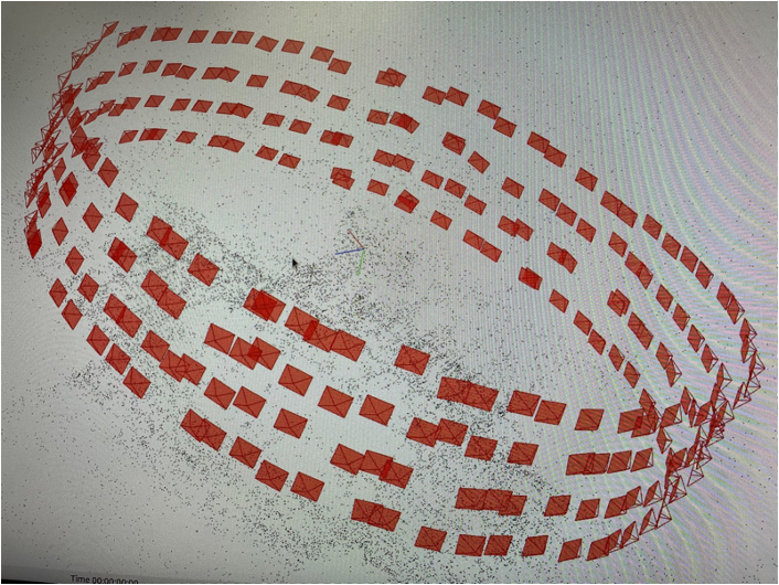 Fig. 8 3D reconstruction of the environment using colmap
Contact: Yang Zhou Jiuhong Xiao